67
The tailrace section1948
Des Joachims, Ottawa River, Ontario/Quebec, Canada
68
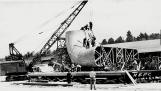
Wooden forms were made to shape the concrete transition to the penstock from the headworks and also the draft tube which directs the water exhausted from the turbine out into the tailrace. These transitions are also known as flumes. This picture shows a draft tube transition form nearing completion beside the carpenter shop.69
The "tailrace section" or outlet "flume frames (forms)" set in the concrete1948
Des Joachims, Ottawa River, Ontario/Quebec, Canada
70
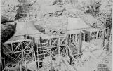
Two draft tube forms (ref. previous image ) are shown set in place in depressions hewn from the bedrock. The forms are then encased in concrete. When the concrete has cured the forms are dismantled and the wood removed leaving the shape of the form in concrete.71
The inlet of the "scroll case" section of a flume1948
Des Joachims, Ottawa River, Ontario/Quebec, Canada
72
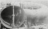
The 'scroll case' is shown with the large circular opening in the foreground. The scroll case is shown oriented horizontally as it will be installed above the draft tube (ref. previous image ). The large opening is the inlet of the scroll case. The inlet is connected to the lower end of the penstock (or large pipe) which feeds water from the upper level of the dam (ref. next image ). The function of the scroll case is to equalize inlet water pressure around the turbine and provide radial inlet water flow to the turbine runner.73
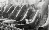
The completed flumes in place1948
Des Joachims, Ottawa River, Ontario/Quebec, Canada
74
Here all 8 units are shown in progressive stages of completion from left to right. The components shown in the 3 previous images are shown here as installed. The units are numbered from left to right; unit 6 transition or flume form shown ready to be connected to the penstock (or large angled pipe). Units 1, 2 and 7 have forms in place ready for pouring the concrete to encase the headworks transition or flume. Unit 6 provides a good view of the installed scroll case (bottom centre of image); note the large circular opening in the top centre of the scroll case where the turbine runner (water wheel) will be installed (ref. next image ).75
Francis Turbine Runner1948
Des Joachims, Ottawa River, Ontario/Quebec, Canada
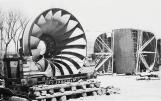
76
A 'Francis Turbine Runner' is shown on its shipping crib. The runner is to be installed in the centre of the scroll case. The runner is shown here on its side. Installation would require tipping the runner trough 90 degrees toward the viewer. The scroll case provides radial inflow of water at the circumference of the runner. The force of the water, changing direction as it flows through the runner, causes the runner to rotate the generator shaft that is connected to it. Water which has given up its energy leaves the runner via the centrally located draft tube to the tailrace.77
The Control Dam1948
Des Joachims, Ottawa River, Ontario/Quebec, Canada
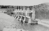
78
By summer 1949 McConnell Lake Control Dam was nearing completion as shown in this photo. Work on the Auxiliary Dam across the Interprovincial Channel was also underway79
The completed flumes in place1948
Des Joachims, Ottawa River, Ontario/Quebec, Canada
80
Summer saw penstock erection nearing completion. The penstocks are the large diameter steel pipes shown angling down from the top of the Main Dam in this picture.In the Powerhouse, work on the steel superstructure continued and the permanent bridge cranes were installed