18
The keel with one knee trial-fitted (not attached). This is the beginning of the backbone assembly. After scarfing and alignment the backbone assembly was blocked into an upright position on a level floor or on the ground. Wooden blocks were located under the keel at the center and both ends and several boards nailed from the floor, or ground pegs, to the stem and sternpost to ensure these were plumb (balanced and aligned).19
Backbone assembly2003
Winterton Boat Building and Community Museum, Newfoundland and Labrador, Canada

20
A hole is bored through the keel to attach the knee with bolts.21
Backbone assembly2003
Winterton Boat Building and Community Museum, Newfoundland and Labrador, Canada

22
The first knee is bolted onto the keel.23
Backbone assembly2003
Winterton Boat Building and Community Museum, Newfoundland and Labrador, Canada

24
The second and third stern knees are attached. These three knees form the support structure for the counter (back) of the boat.25
C-clamps2003
Winterton Boat Building and Community Museum, Newfoundland and Labrador, Canada

26
C-clamps are essential to secure the pieces during trial-fitting.27
Backbone assembly2003
Winterton Boat Building and Community Museum, Newfoundland and Labrador, Canada

28
The stem is attached to the keel with a piece of deadwood.29
Counter2003
Winterton Boat Building and Community Museum, Newfoundland and Labrador, Canada

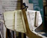
30
The counter, built from two-inch planks joined edge to edge using wooden pegs or nails, is cut to the desired shape.31
Counter2003
Winterton Boat Building and Community Museum, Newfoundland and Labrador, Canada