14
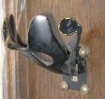
Switch-hook LatchCirca 1950
Saskatchewan, Canada
15
This Magneto Automatic Wall Telephone is rather unusual, it used a crank to call parties on the same line and the dial to call other lines. To prevent inadvertent interruption of another partys dialling, a switch-hook latch was used. When the handset was removed from hook, user could listen to determine if line was free, he would then depress latch to allow dialling.It is believed these were only used in Saskatchewan.
16
Step-by-Step Automatic Switching1920 - 1980
Throughout Canada
17
The Step-by-Step (SxS) switching system took the switching away from operators and their switchboards. There are three main type of switches required to connect calling and called subscriber:Linefinder, its finds which subscriber amongst 100 or 200 is requesting service and connects it to the next switch a Selector,
Selector, of which there are usually five provides dial tone, and responds to the first five digits dialed to route the call to the last switch a Connector,
Connector connects to the appropriate called subscriber by stepping to the level corresponding to the 6th digit dialed, then rotating to the position matching the last digit dialed.
Each switch is very complex, it has at least 7 relays and three electro-magnets, a vertical shaft with wipers to contact the bank of contacts for making a connection. Northern's shops made every one of the hundred of parts of these switches other than a casting which they plated and machined.
18
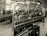
Step-by-Step ShopCirca 1964
Montr�al, Qu�bec, Canada
19
This is last stage of the Step-by-Step (SxS) shop where the switches are adjusted and tested on 20 capacity shelves prior to packing and shipping to telephone offices. The SxS shop employed a great number of people on two floors of one wing of the Shearer plant.20
Step-by-Step OfficeCirca 1969
Montr�al, Qu�bec, Canada
21
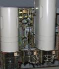
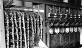
A partial view of Selector Step-by-Step Switches in a telephone office, this particular frame was 11 foot 6 inches high and contained 160 switches. A large telephone office could have a few hundred frames similar to these. An office operating at a busy time of the day was very noisy with switches operating and releasing continuosly in the hundreds. Since these switches had a lot of moving parts, they required lubrication, cleaning, adjustment and replacement of worn parts. This necessitated a large number of technicians for maintainance purposes, a large office could easily have 80 people.22
Step-by-Step WiringCirca 1973
Throughout Canada
23
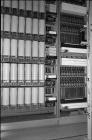
This view shows the wiring at the rear of a Line Finder frame. The wiring in the foreground connects the customer lines to their relays and to the the linefinders which are to the right. A huge amount of wiring is required as can be seen to the right. The large bundle of wires connect to the banks of contacts which each have 1200 wires. A new large office would take months to install due to large number of equipment frames and huge amount of wiring with each connection requiring stripping the insulation off the wires, making connections and soldering each one.24
Step-by-Step OperationCirca 2007
Throughout Canada
 Credits:
Ken Lyons
25
This short clip shows a complete seven digit call, first the Linefinder steps up to the required level and rotates to find calling subscriber, it then seizes the first selector which returns dial tone to indicate its readiness to accept dialing. It then steps to the level dialed and rotates to find a path to the next selector. The second to the fifth selector operate in the same manner with the exception of the fifth, it connects to the last switch a Connector which steps to the level matching the sixth digit dialed. It then rotates to the position matching the 7th digit dialed. The Connector tests the line to ensure it's idle and it will apply ringing to the line, otherwise it returns a busy tone.A wireless set was used for the video, normally a rotary dial would have been used. When Touch Tone was introduced in the 1960s, it was unavailable for those who were served by Step-by-Step offices. The pressure was so great on telephone companies to provide Touch Tone that converters were added between the Linefinder and the first Selector so a Touch Tone phone could be used. Ironically this was slower than rotary dialling. Later push button phones could pulse instead of sending tones.
26
35F Current Flow Test Set1920 - 1980
Throughout Canada
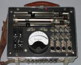 Credits:
Telecommunications Museum