14
In the early 1950s Step-by-Step switching was no longer meeting the higher traffic volumes and number of lines. It required far too much equipment and too much maintenance to be cost effective.A new switching system called cross-bar (X-Bar) was introduced. It used nearly half as much space as Step-by-Step and required significantly less maintenance as it didn't use electro-mechanical switches.
X-Bar required users to adapt to it because the called phone would not ring immediately after dialed. The system had to process the dialed number by the use of about 11 different massive frames of equipment that were each made up of hundreds of relays.
In the telephone office, where the Step system was quite noisy, for it was a constant noise, on the other hand the X-Bar made an aggressive noise because of the large number of relays operating simultaneously.
15
Crossbar Local CableCirca 1969
Montr�al, Qu�bec, Canada
 Credits:
Northern Circuit - Autumn/Winter 1969
16
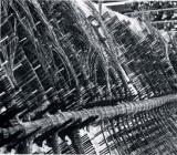
Crossbar like Step-by-Step required a tremendous amount of wiring. Where in the past wiring was done wire by wire to all the individual connections, in Crossbar large local cables were made up on a sheet of plywood that had nails placed where the cable would break out. This would facilitate the actual wiring of the equipment.Another innovation was the use of gun wrapping wires to slender terminals, this eliminated the use of soldering and reduced labour effort.
17
Microwave TransmissionCirca 1958
Throughout Canada
 Credits:
Northern Circuit - Fall 1958
18
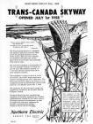
With the advent of television there was a need to have a network to carry this new medium. Carriers of the forties and fifties could handle voice but not video, they didn't have the bandwidth to do so because one video signal channel needs about the same bandwidth as 600 voice channels. A conventional carrier of the day could carry 12 voice channels.A new type of carrier was required and microwave radio would fit the bill. It could handle as in the case of the Trans-Canada Skyway 12 one-way radio channels. Each pair of channels could carry either 720 voice circuits or one two-way video channel and 120 telephone circuits. The voice and video signals are first multiplexed, (mixed and raised in frequency), then amplified, conveyed to antennas on top of tower by hollow wave guides and out of the antenna. Each tower must be within eye-sight of the next because microwaves travel in a straight line.
The first link: Buffalo, Toronto, Ottawa and Montreal was opened in 1953. The coast to coast network was launched in 1958.
19
TD-2 Microwave Transmitter BayCirca 1958
Throughout Canada and USA
 Credits:
Bell Canada Historical Collection
20
The American designed TD-2 microwave equipment bay, where multiplexed signals are transformed then sent out by the rectangular waveguides on to the tower. Northern subsequently designed their own Microwave radio systems from the analog "RA" series to the digital "RD" series along with "MA" series multiplex systems.21
Signalling UnitsCirca 1963
Montr�al, Qu�bec, Canada
 Credits:
Ken Lyons
22
The Microwave system could carry a very large number of voice circuits. In order to transmit a large number of voice circuits these must first be multiplexed by carrier equipment. A voice circuit also needs to send its status, whether it is busy or not and it must convey the called number. This was achieved by signalling units that would send a constant tone within the voice band when the circuit was idle. When busy the tone was absent. When signalling digits, the tone would switch on and off to match the dial pulses. In a large telephone toll office there could be several thousand of these signalling unitsBecause the tone used was within the voice band there was risk that a person might reproduce that tone in speech and cause the circuit to disconnect itself. The designers felt it was unlikely to happen since the tone had to be held for a long duration. Well it just so happened the president of a large telephone company sustained that tone in his normal speech and he kept talking himself off his toll calls. The signalling circuits were subsequently designed to eliminate this deficiency.
.
23
Princess TelephoneCirca 1965
Throughout Canada
 Credits:
Northern Circuit - Summer 1965
24
The Princess phone was designed with women in mind. They demanded a small attractive phone that could be used in the bedroom. This was a challenge to the designers because the component used for the standard model 500 set were too bulky save for the handset. A new smaller network and ringer were designed to fit in the housing which was only slightly larger than the handset. It had a dial light that illuminated the dial with a dimmed light when not in use but would be brighter when handset was removed for dialling.25
Touch Tone Dials1965
Globally
 Credits:
Northern Circuit - Summer 1965
26
Touch Tone, Bell's trademark, also known as Digitone was introduced in 1965. Note original key set had only ten buttons, in those days when you called a real person answered. The * and # buttons were introduced a few years later. Telephone companies charged a premium because these phones were more expensive and additional equipment in the telephone office was required to decode the tones.27
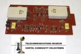
Early Printed Circuit BoardCirca 1969
Throughout Canada